The circuit is called a guitar preamp, but actually not, because the gain is close to 1. However, due to its impedance, thereby allowing transmission with better sound quality using a long cable between the guitars and amps.
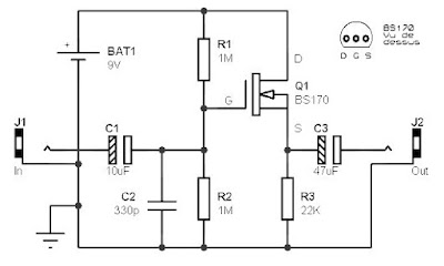
The Guitar pre amp circuit is based on a FET-type BS170, and require very little support components. The polarization of the gate (G, gate) of FET is provided by two resistors R1 and R2. Both resistors are also to set the input impedance of the assembly, which here is close to 500 ohms. The original scheme, the second resistor set at 92K each, and keep the input impedance of less than 50K, which may be too tight to plug the guitar.
BS170, As usual with this type FET or MOSFET power transistors smaller (TO92 plastic housing in particular), you should check the pin manufacturer in the document (datasheet), with consideration for the brand, because the manufacturers do not necessarily offer the same pinouts for the same component model. The BS170 is here using the Motorola brand and pinout is as follows.
Related Posts :
Subwoofer amplifier with 30W output powerAmplifier circuit is very suitable for use in subwoofer amplifier system based on IC SI1030G. Amplfi… Read More...
50W audio amplifier with IC'sThe above amplifier circuit based on IC is STK075G, and another equation that is STK084G, STK085, ST… Read More...
2 X 0.6W schematic audio amplifierThis schematic have require minimum voltage at 1Volt and maximum volotage at 9 Volt. Maximum output … Read More...
Mini and simple power amplifier circuitsWhat is the meaning of the picture above? The above picture is a miniature audio amplifier and very … Read More...
20W amplifier schematic with muteThis is a series of audio amplifier using ic and equipped with a mute switch. This circuit using ic … Read More...
140W audio amplifier with IC STK070By using the above amplifier circuit you can hear the sound quality is quite good by a high output p… Read More...
0,15Watt amplifier schematicAmplifier circuit is also very suitable when used in fm radio receiver. Supply voltage required 8 - … Read More...
20W Surround audio amplifier with SI-1020GHave you been use the IC above? if those who have not, IC above is used or applied to the audio powe… Read More...
2 x 2,3 Watts power amplifier schematicsDo not misunderstand, this series is one of several series of power amplifiers that have output / lo… Read More...
6 - 12 Volt audio amplifier circuitsThe above is an amplifier circuit using supply voltages from 6 volts DC to 12 Volt DC. Power output … Read More...
2 X 40 Watt STK amplifierComponents of the above is one component of ic which is applied as a reinforcement. Power amplifier … Read More...
70W STK amplifier schematicFor this amplifier circuit using three voltage plus, min, and the ground. with a maximum voltage app… Read More...
2 X 50W ICs amplifier with STK4191The above is a stereo amplifier circuit based on IC STK4191 with 2 X 50Watt output power 8 ohm imped… Read More...
150W amplifier with active crossoverSeries 150W Amplifier With Active Crossover Series 150W Amplifier with Active Crossover is very inte… Read More...
Stereo 30W STK ICs amplifier circuitThis amplifier circuit based on IC STK ic used in which the manifold. And on this circuit ic STK has… Read More...
TDA2003 Car amplifierThis is a very popular series of amplifiers audio users who require maximum aduio results and of cou… Read More...
2W PA246 amplifier circuitThis amplifier output circuit having a fairly low at only 2W 8 ohm impedance. Minimum supply voltage… Read More...
TDA2004 stereo bridge audio amplifierMost of the lovers, especially in audio electronics, it will never escape from this one component of… Read More...
0,4W power amplifier with 5G37 ICThis circuit requires a voltage of 6-12 Volts. To have a good quality of this series with the volta… Read More...
50W car audio amplifier schematic circuitsCar power amplifier uses SI1050GL IC as the main amplifier. The output power 50 Watt 8 ohm mono impe… Read More...
0 Response to "Guitar pre amp circuit is based on a FET-type BS170"
Post a Comment