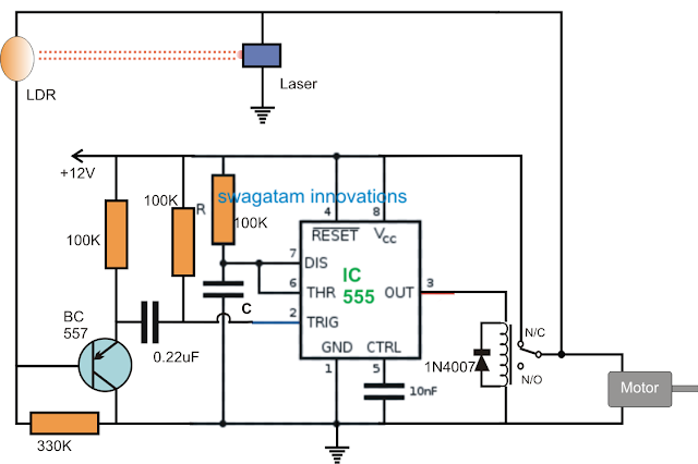
The material storage level indicator circuit as requested above can be built using the following simple configuration:
The Design
The functioning of the circuit can be understood as given below:
When power is first switched ON, the supply powers the 555 circuit and simultaneously also switches ON the motor, and the laser through the relay N/C contacts causing a low resistance on the receiving LDR device.
The low resistance from the LDR inhibits the BC557 from conducting and the situation locks in this condition, until the space between the Laser/LDR begins filling with the relevant material.
As the material begins filling, at some point of time it reaches the threshold level between the LDR/laser communication beam, and interrupts the beam.
As soon as this happens, the LDR resistance becomes high allowing the BC557 to conduct and trigger theIC 555 stage which is actually wired as a standard monostable multivibrator circuit.
The IC 555 triggers into action and in the course activates the relay. The relay contacts change position from N/C to N/O, which instantly cuts-off power to the laser and LDR network and the motor, as requested by the user.
The situation is sustained until the set time of the monostable lapses and the relay reverts to its earlier N/C position. The circuit now attains its original standby position and activates the motor, until the storage is full again.
The proposed material storage level controller circuit can be further enhanced with an alarm indication by suitably attaching a 12V alarm circuit with the N/O contact of the relay so that whenever the storage is full, the relay disables the laser and also activates the associated alarm.
The value of C can be determined with respect to the 100k resistor from this IC 555 calculator software.

0 Response to "Material Storage Level Controller Circuit"
Post a Comment