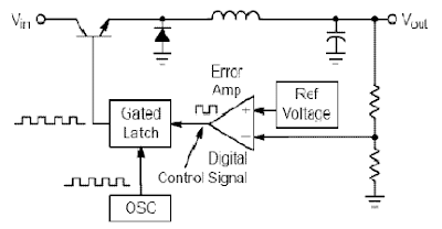
Switching regulator subsystems intended for use asdc to dc converters. 3V to 40 Volt DC Converter circuit | The use of switching regulators is becoming more pronounced over that of linear regulators because the size reductions in new equipment designs require greater conversion efficiency. Another major advantage of the switching regulator is that it has increasednapplication flexibility of output voltage. The output can be less than, greater than, or of opposite polarity to that of the
input voltage.
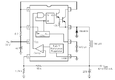
The MC34063 series is a monolithic control circuit containing all the active functions required for dc to dcconverters. This device contains an internal temperature compensated reference, comparator, controlled duty cycle oscillator with an active peak current limit circuit, driver, and a high current output switch. This series was specifically designed to be incorporated in step–up, step–down and voltage–
inverting converter applications. These functions are contained in an 8–pin dual in–line package.
FEATURES 3V to 40 Volt DC Converter :
· Wide Input Voltage Range 3 V to 40 V
· Precision Internal Reference 2%
· High Output Switch Current Up to 1.5 A
· Short-Circuit Current Limiting
· Adjustable Output Voltage
· Low Standby Current
· Oscillator Frequency Up to 100 kHz
Related Posts :
3V to High voltage inverterInverter circuit on basic of really taking a series of mosquito racket, a racket in which these mosq… Read More...
Simple Inverter circuit with IC556 timer chipThis circuit is low power inverter , in this circuit only save a few components, about 9 parts. Volt… Read More...
DC- DC Converter 12V to 24VThis simple circuit is a DC-DC converter that converting up 12V source to a 24V. It can be used to r… Read More...
12V to +/- 20V DC Converter Circuit100 Watt 12V to +/- 20V DC Converter CircuitDC To DC Converter circuit used to be an convert v… Read More...
6 to 12 Volt ConverterBelow its a converter circuit voltage from 6 Volt to 12 Volt DC.6 Volt to 12 Volt DCPart List :R1, R… Read More...
Simple Inverter with Two TransistorsThe series below is a simple inverter circuit that will change the voltage of 12v dc to 220v ac, wit… Read More...
Inverter 12V to 115V with 25 W power outputLow power inverter schematic are only use 9 components , one of which IC 556 , TIP120 NPN Darlington… Read More...
Mosfet Snubber Flyback Converter CircuitMosfet Snubber Circuit in Flyback Converter , Typical flyback convertor with drain clamping cir… Read More...
12V to 220V Inverter Schematics12V to 220V Inverter Circuit Diagrams, Even though today’s electrical appliances are increasingly of… Read More...
6V to 220V inverter schematicCircuit schematic above is one of the voltage inverter circuit, starting from 6-Volt input on the DC… Read More...
3V to 40 Volt DC Converter CircuitSwitching regulator subsystems intended for use asdc to dc converters. 3V to 40 Volt DC Converter ci… Read More...
Inverter 5000 Watt PWMThis inverter uses PWM (Pulse Width Modulator) with type IC SG3524. IC serves as a oscillator 50Hz, … Read More...
Simple Inverter Circuit from 12 V up to 120V elevatedThis is a simple 120 V : 24 V , center - tapped (CT) control transformer and four additional compone… Read More...
Frequency to Voltage Converter CircuitIC LM2917 Frequency to Voltage ConverterIC LM2917 IC chip is designed specifically as a Frequency to… Read More...
10Mhz to 1 MHz Frequency Converter10Mhz to 1 MHz Frequency Converter CircuitPart ListIC1 7404 = 1IC2 7490A = 1R 1 K = 2R 3.3 K = 1C Tr… Read More...
0 Response to "3V to 40 Volt DC Converter Circuit"
Post a Comment