This Powerfull audio amplifier can provide a 2kW power peaks, and 1.5kW continuously, which means that the amplifier can burn your most famous speakers. To provide this power in action you can connect (What do I highly do not recommend), two series-connected 8-ohm speaker in AC 220. In this case the dynamics will be on the same 110V current voltage into 8 ohms – 1,500 W. What do you think will last a long time whether in this mode acoustics.
Transformer 2 x 90V will give no-load voltage ± 130V (260V between the outermost points of the rectifier), so that the power supply to operate with extreme caution.
Bipolar transistors were chosen as most appropriate for end-stage of the amplifier. This is primarily dictated by the voltage that exceeds the boundary voltage for the majority of MOSFET transistors. It’s as much and for bipolar transistors, but MJ15004 / 5, or MJ21193 / 4 correspond to the maximum voltage requirement, and therefore, we shall discuss them.
Next, you need to think about the dissipation of excess capacity on the transistors and the intensity of their cooling. Since at 65V under load (worst case) power dissipation will be …
P = V? / R = 65? / 4 = 1056W
That is equal to the average electric heaters …
Remember, when working on a resistive load with 45 ° phase shifts power dissipation is almost doubled. From this it follows that a good cooling is essential for this amplifier, you need a good radiator, cooling fans for forced cooling (natural convection does not help).
MJ15024 / 5 (or MJ21193 / 4) transistors in the case of K-3 (iron with two pins as KT825/827), and calculated to scatter 250W at 25 ° C. Housing K-3 transistor chosen because it has the highest rated power dissipation, because the thermal resistance is lower than that of any other transistor in a plastic case.
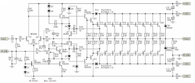
MJE340/350 in the voltage amplifier stage provides good linearity. But even with the current through a cascade of 12mA, Power – 0.72W, so that Q4, Q6, Q9 and Q10 must have heat sinks. Transistor (Q5), the offset bias adjustment must be installed on a common heat sink with okonechnikom and a reliable thermal contact.
Short-circuit protection circuit (Q7, Q8) limits the current at 12A and the power is allocated one transistor around 175W, while long-term operation of the amplifier in this mode is not allowed.
Additional elements of the feedback (R6a and C3a, as shown dotted) are optional. They may be needed in case of self amplifier. Backward diodes (D9 and D10) to protect the transistors of the amplifier back-EMF at work on a resistive load. Diodes 1N5404 series can withstand peak currents up to 200A. Rated voltage should be at least 400V.
Resistor VR1 100 Omo used for balancing the DC amplifier. With component values shown in the diagram, the initial offset must be within ± 25mV, before setting up. Resistor VR2 is used to set the quiescent current bias adjustment. Adjust the idle current by measuring the voltage across the resistor R19 or R20 which should be within 150mV. Sensitivity input stage – 1.77V for 900W into 8 ohms, or 1800W into 4 ohms.
Related Posts :
Stereo STK013 audio amplifier circuitOn the amplifier circuit using ic STK, the same as my previous posting. However, in the above circui… Read More...
140W audio amplifier with IC STK070By using the above amplifier circuit you can hear the sound quality is quite good by a high output p… Read More...
TDA2004 stereo bridge audio amplifierMost of the lovers, especially in audio electronics, it will never escape from this one component of… Read More...
2 x 2,3 Watts power amplifier schematicsDo not misunderstand, this series is one of several series of power amplifiers that have output / lo… Read More...
150W amplifier with active crossoverSeries 150W Amplifier With Active Crossover Series 150W Amplifier with Active Crossover is very inte… Read More...
2 X 0.6W schematic audio amplifierThis schematic have require minimum voltage at 1Volt and maximum volotage at 9 Volt. Maximum output … Read More...
0,15Watt amplifier schematicAmplifier circuit is also very suitable when used in fm radio receiver. Supply voltage required 8 - … Read More...
6 - 12 Volt audio amplifier circuitsThe above is an amplifier circuit using supply voltages from 6 volts DC to 12 Volt DC. Power output … Read More...
20W Surround audio amplifier with SI-1020GHave you been use the IC above? if those who have not, IC above is used or applied to the audio powe… Read More...
50W car audio amplifier schematic circuitsCar power amplifier uses SI1050GL IC as the main amplifier. The output power 50 Watt 8 ohm mono impe… Read More...
2W PA246 amplifier circuitThis amplifier output circuit having a fairly low at only 2W 8 ohm impedance. Minimum supply voltage… Read More...
60W ICs amplifier with OM961Amplifier circuit is very suitable for use in car audio speakers that use a subwoofer, with a power … Read More...
2,5 Watt audio amplifier circuit diagramThe above is a simple amplifier circuit also has a minimal power output. By using only a few compone… Read More...
Subwoofer amplifier with 30W output powerAmplifier circuit is very suitable for use in subwoofer amplifier system based on IC SI1030G. Amplfi… Read More...
2 X 30Watt home amplifier circuitAudio amplifier circuit is very suitable for use at home, using a subwoofer speaker, or woofer speak… Read More...
50W audio amplifier with IC'sThe above amplifier circuit based on IC is STK075G, and another equation that is STK084G, STK085, ST… Read More...
Mini and simple power amplifier circuitsWhat is the meaning of the picture above? The above picture is a miniature audio amplifier and very … Read More...
70W STK amplifier schematicFor this amplifier circuit using three voltage plus, min, and the ground. with a maximum voltage app… Read More...
2 X 40 Watt STK amplifierComponents of the above is one component of ic which is applied as a reinforcement. Power amplifier … Read More...
Subwoofer amplifier schematic diagramAmplifier circuit is very suitable for use in subwoofer speaker, because its strong. This circuit us… Read More...
0 Response to "1500W Power Amplifier Circuit"
Post a Comment